DUR O LOK® COUPLINGS
INSTALLATION PROCEDURE
Dur O Lok Installation Instructions (PDF, 681KB)
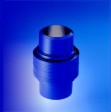
Figure 1. Exploded View of DUR O LOK Coupling.
1. Prepare DUR O LOK® Coupling for Welding
- The welding surfaces of the coupling and the mating pipe must be cleaned and prepared for welding. Be sure to remove any dirt, grease, or other surface contaminants prior to welding. Also, be sure to remove plastic protective caps prior to welding, as they will melt. If the coupling has a black oxide finish, lightly grind or sand off the black oxide coating from the welding surfaces of the coupling. Removal of the black oxide coating from the couplings welding end may have already been done at the factory for your convenience.
- For applications that involve catalyst transfer (e.g. CCR Platforming), it is recommended that the black oxide coating is removed from the entire inner surface of the coupling.
2. Weld DUR O LOK® Coupling to Mating Pipe
- It is highly recommended that the DUR O LOK Coupling be welded to the mating pipes as an assembled unit when possible, as this will ensure proper alignment and protect machined surfaces. DUR O LOK Couplings have higher installation tolerances than standard flanges, and extra care must be taken during welding alignment.
Warning: Do not have gasket in place while welding, as damage will occur.
- For installation of DUR O LOK Couplings in catalyst lift lines, or similar services where long piping runs are involved, tack weld the assembled coupling to both pieces of pipe positioned horizontally along a flat surface. Care must be taken to ensure that the two pieces of pipe are straight and aligned prior to welding. 80 feet of (shop floor) space is required to position and weld two 40 foot sections of pipe to a DUR O LOK Coupling. The tacked DUR O LOK Coupling may be disassembled prior to completing the circumferential weld.
- For pipes involved in catalyst transfer, a smooth transition at the inside surface for all circumferential welds is mandatory. The inside diameters of the pipes and welded DUR O LOK Coupling may require grinding to remove all ledges to produce a flush transition in the area of the circumferential welds. The final wall thickness of the pipes and DUR O LOK Coupling must not be less than the minimum required wall thickness.
- For pipes employing precision bends (e.g.- CCR catalyst transfer lines and related applications), trial installation in the shop is highly recommended, as it allows for final adjustments to be made. DUR O LOK Couplings have higher installation tolerances than standard flanges, and extra care must be taken during final alignment. Pipe sections must be match marked after trial fit-up is complete & on-spec. This will facilitate trouble-free installation of the pipe assemblies in the field.
- For non-horizontal coupling installations, ensure that the female hub (hub with gasket cavity) is positioned as the lower half of the coupling so the gasket cannot fall out of place during assembly.
- Welding of 304SS DUR O LOK Couplings to carbon steel pipe is acceptable.
Warning: Protect Machined Surfaces of Coupling from Weld Splatter.
3. Position Tapered Retaining Ring
- Place the tapered retaining ring over the male hub end and slide it past the grooves on the hub for the split-coupler. The end with the larger inside diameter must be oriented toward the mating (gasket) surface of the coupling. The two set screw holes should be located in the half of the tapered retaining ring closest to the mating surface of the coupling.
- Bring the two hub ends welded to the pipe segments into approximate assembled position.
4. Install Gasket
- DUR O LOK Couplings are offered in a standard and high temperature design. Standard design couplings employ an elastomeric type o-ring seal and are used for applications typically below 450° F (232° C). The o-ring material determines the temperature limit. Materials of construction for o-rings include Viton®, silicone, Kalrez®, and many others depending on the application requirements. Although o-rings are typically reusable if not damaged, it is strongly recommended that a used o-ring be replaced.
- BETE offers a high temperature DUR O LOK Coupling design which employs a graphite type flat gasket for nominal service temperatures above 450° F (232° C). A DUR O LOK installation clamp may be required to compress the installed gasket and properly assemble the high temperature DUR O LOK Coupling. These gaskets are not reusable. These custom sized gaskets are available only through BETE. Please specify DUR O LOK Coupling pipe size and pipe schedule when ordering.
Warning: Low Temperature (OR76) and High Temperature (GRF100) Design DUR O LOK Couplings and their Gaskets are NOT Interchangeable.
- Closely examine the gasket cavity of the female hub. Ensure that the cavity is free from oil, debris, scratches, or anything that may affect the quality of the seal.
- Place the gasket in the gasket cavity of the female hub.
- Handle gaskets with care in order to avoid damage.
Warning: Damaged gaskets must not be used, as they will not seal properly.
Always Replace Used Gaskets to Ensure Proper Seal.
High Temperature (GRF100) Gaskets are for One-Time Use Only.
5. Assemble Coupling
BETE offers a special clamp used to bring together hubs that are slightly misaligned (REF Figure 3, purchased separately). If this clamp is to be used refer to DOL Clamp Instructions (PDF, 928KB) for more details on its use.
- With the gasket in place, draw the hub ends together. If the welded pipes are not aligned properly, a clamp will be required to draw the two halves of the DUR O LOK Couplings together. If desired, a clamp can be constructed in your shop using standard riser clamps, as depicted in Figure 2. Couplings that are excessively out of alignment will require removal, repositioning, and re-welding. It is best to take care to align the piping and couplings prior to welding.
- Place the two split couplers in position with the set screw groove in the split couplers being positioned over the female hub (hub with the gasket).
- Slide the end with the larger inside diameter over the split couplers until the tapered retaining ring is in position with the set screw holes directly over the set screw groove in the split couplers. Use a soft faced hammer (e.g. nylon or rubber) to drive the tapered retaining ring into a fully engaged position.
Warning: The tapered retaining ring must be fully engaged to attain the design compression and pressure rating for the desired service. The tips of the set screws must fit completely inside the split couplers set screw groove. The coupling could become inadvertently disassembled from vibration during use if not assembled properly. The result may be process material leakage.
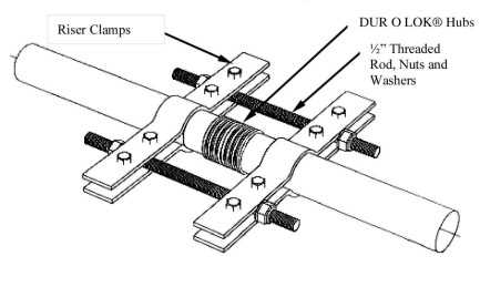
Figure 2. Assembly clamps can be made in the field with standard riser clamps. BETE made clamps are available for purchase. Reference DOL Clamp Instructions (PDF, 928KB) for usage of BETE made clamp.
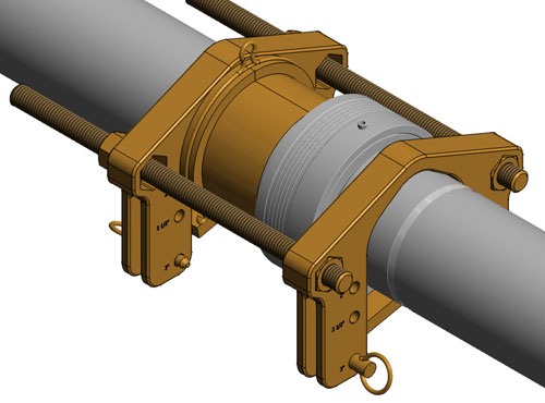
Figure 3. BETE made clamps are available for purchase. Reference DOL Clamp Instructions (PDF, 928KB) for usage of BETE made clamp.
6. Secure Coupling
- Install and hand tighten the set screws with the supplied 3/16" hex key (allen wrench). The function of the set screws is to prevent the tapered collar from becoming disengaged. The set screws do not function to pull the tapered retaining ring into position. Do not over-tighten, as damage to the threads may occur.
- Install the safety wire through the holes in both set screws and wrap the wire once around coupling.
- Twist the safety wire a minimum of five times such that the set screws can not work loose during operation. Safety wire twisting-cutting pliers are available for this purpose.
- The presence of the safety wire generally is indicative that a gasket is in place. The DUR O LOK Couplings can also be tagged or marked to indicated "gasket installed".
Dur O Lok® manufactured by